Showing posts with label Electronics. Show all posts

Sunday, June 23, 2013

SMD-Codes Databook 2010 Edition

SMD-Codes Databook 2010 Edition


2010 edition SMD-code databook in PDF format from a known author Eugene Turuta presents the SMD-codes for active semiconductor components. This book includes now 120.300 SMD-codes for different semiconductors like diodes, thyristors, transistors and ICs.


Download Here:


RBT(c)2013
5000 Integrated Circuit Power Audio Amplifier
5000 integrated circuits - power audio amplifiers. A new data book in electronic format from a known author Eugene Turuta presents the integrated circuits - power audio amplifiers. This book includes about 5,000 integrated circuits - power (final) audio amplifiers.
 
Download Here: 
5000 Integrated Circuit Power Audio Amplifier
RBT(c)2013

Tuesday, April 16, 2013

5 Bands Graphic Equalizer


Based on the famous BA3822LS equalizer chip.


Introduction:

Many times when we hear a song we feel the need to change the parameters of the original EQ, adjusting this to our liking. While a song is recorded, mixed, equalized and mastered by experts, it is impossible to make a mix to suit the taste of each, which is different according to your personal settings and cultural environment that surrounds the listener. 
This is the moment we need an equalizer. Normally found three band EQ (Low, medium and high), but sometimes we fail to balance sound we want. 
To reduce this problem we have an equalizer that divide the audible aspect in more parts. In this paper we present a 5-band equalizer gives us the ability to "color" a little better our favorite songs.


What is an EQUALIZER?


The equalizer is a sound processor to split the original audio signal and modify the volume level independently. Each signal portion is called Band. Each band is responsible for increasing the volume of a certain frequency range. The human hearing range is from 20Hz , up to 20kHz . This EQ has 5 band-pass filters consist of capacitors and potentiometers that filter the desired frequency band. 
Band peaks are affected by this EQ: Bass ( 100Hz ), middle income ( 330Hz ), middle ( 1kHz ), upper middle ( 3.3kHz ) and high ( 10kHz ).

The materials of the 5-band stereo equalizer are very cheap and easily available. Check before starting the assembly of the circuit you have on hand all the necessary components for assembly. So the work is done faster and nicer, and there's nothing more boring than having to be traveling to get what you missed. For this we must carefully review the list of materials found in the PDF file and compare with the mask components, which we will use as a guide for the correct assembly of the circuit. It should be very careful when placing each component in place. Electrolytic capacitors, regulator and integrated circuits must respect the established polarity.


The integrated circuit BA3822LS stereo graphic equalizer is a five-point frequency control. BA3822LS has two channels within five center frequencies of each channel can be independently set using external capacitors. 
This IC has a wide feeding range, ranging from 3.5 volts to 14 volts DC. The integrated package is 24-pin SOIC or SZIP. This makes it an ideal choice for home stereo systems, for their videoke or for use as an equalizer in the car. 
Inside BA3822LS has 10 operational amplifiers. This facilitates the assembly of the circuit, reducing space and with a very affordable price.


Assembly:

We put all the resistors in place. The wrong placement of a part could cost us time and money. Then proceed to solder the resistors.


Next is to insert and solder all the capacitors, starting with ceramic type then Mylar. Since this capacitors doesn't have POLARITY, you can insert it in any direction..Just double check the value of the capacitors.
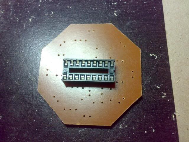
The 8 pins IC socket has a NOTCH on the other end to indicate the proper placement of the IC later..Follow the placement on the parts placement guide. 


Observed the placement of IC SOCKET!

Double check the VALUE of capacitors based on PARTS PLACEMENT GUIDE  printed on the PCB.

Electrolytic capacitors are POLARIZED devices . For this reason it is very important to check the PARTS PLACEMENT guide for the proper POLARITY before placement. 
To identify the polarity of a capacitor, note the white stripe with a minus sign, this is the negative lead of the capacitor. Also their polarity may be identified as its positive terminal is longer than the negative terminal. 
On the PARTS PLACEMENT GUIDE, a circle with a small DOT that indicates the negative lead of the Electrolytic capacitors.


Proper placement of Electrolytic capacitors.

 The circuit has a built-in rectifier diode, filter and regulator, so you can power it with AC or DC source..

Bridge rectified diode.

The regulator LM7809 delivers a voltage of 9 volts and a current of up to 1 amp. Our EQ regulator can be supplied with 12 - 24 VDC without any problems. Identifying a regulator should be noted that the letters LM corresponding to the mark of the component. In this case belongs to the American company National Semiconductor, which manufactures electronic components. The next two numbers ( 78 ) mean that the regulator is positive and the last two numbers ( 09 ), determine the output voltage of the regulator. In this case, 9V delivery. Remember that this controller can only be supplied with a voltage below 32 volts DC, if for some reason is supplied with a higher voltage, the regulator will burn. 
A regulator needs a DC voltage of at least 3 volts above the voltage delivery. For this reason we recommend feeding the circuit with at least 12 volts AC. If the transformer is too low, we will not get at least 3 volts above, necessary for the regulator to do its job and give us 9 volts.

LM7809, 9 volts regulator.

In the picture you can see the filter capacitor after bridge rectifier diode. This capacitor can be 1000 uF to 2200 uF at least 25VDC. Its function is to load and maintain voltage so that it does not fall at the end and beginning of each half cycle, thus converting alternating current (AC) into direct current (DC). can also observe three-pin connectors (GP). These connectors are very useful when removing the equalizer for maintenance or repair. The connector power input we have removed the center pin.
Power supply section.

The integrated circuit TL072 is a high performance dual op amp. 
As BA3822LS has no gain, ie outputs a signal of the same volume that you get, We make this operational to give a bit of gain to the signal. Resistors 2.2K going to the inverting inputs 2 and 6 respectively and 100K resistors ranging between inputs and outputs of the integrated, are responsible for the gain. 100K 2.2K Dividing, we get a gain of 45. 

If you need more gain, only 2.2K resistors change by about 1K. But if you just want to decrease the gain, can be altered 5.6k resistors, up to 10K. 
The TL072 can replace the JRC4558 , the TL082 or NE5532


Insert and solder the dual 50K potentiometers for the equalizer controls and the dual 20K potentiometer for the volume control. 

Before testing the circuit, inspect the PCB against the light, that has no short between tracks. Clean the PCB with a toothbrush and lacquer thinner, to remove grease and possible solder particles remain attached after soldering. 

Finished equalizer board.


 Download the schematic and PCB layout here: Schematic and PCB


 Original link HERE


Sunday, February 3, 2013

Working With USB SPI Programmer

Lots of people are asking for some pictorial guides on proper placement and mounting of SOIC/WSON8 chip on USB SPI. 

So here it is.just follow the guide closely..


Voltage selector and Pin numbering.


Be sure to properly insert the pins on ZIF socket.


24Cxx I2C EEPROM placement.

25/26 Series EEPROM Placement.

My preferred placement.

This is the MOST IMPORTANT and often IGNORED! Don't forget the INSULATOR!

SOIC8 to SOIC16 connection.


RBT(c)2012


Monday, January 9, 2012

TV/DVD I2C, SPI EEPROM Programmer Complete Tut!

Here is a video tutorials on how to install, register, activate and used TV/DVD I2C, SPI EEPROM Programmer.


 How to install and register:


Driver Installation:


How to work with the programmer:


Enjoy using your new programmer!


Download the latest installer HERE: 


RBT(c)2011


Friday, August 19, 2011

Digital LC Meter

PIC Digital LC Meter:
This is one of the most accurate and simplest LC inductance / capacitance Meters that one can find. This LC Meter allows you to measure incredibly small inductance starting from 10nH to 1000nH, 1uH to 1000uH, 1mH to 100mH and capacitance from 0.1pF up to 900nF. LC Meter's circuit uses an auto ranging system so that you do not need to spend time selecting ranges manually. Another neat function is reset switch that will reset the initial inductance / capacitance, making sure that the final readings of the LC Meter are as accurate as possible.


LC Meter's Technical Specifications:

Voltage Supply: 6 - 16V
Accuracy: 1%
Full Automatic Ranging
Inductance Resolution: 10nH
Capacitance Resolution: 0.1pF

LC Meter's Inductance Measurement Ranges:      
- 10nH - 1000nH
- 1uH - 1000uH
- 1mH - 100mH

LC Meter's Capacitance Measurement Ranges:    
- 0.1pF - 1000pF
- 1nF - 900nF


Prototype testing:
Meter with no DUT attached.

Testing a 15pF NPO ceramic cap.

Another 22pF ceramic cap.

"L" mode calibration.

Reading a 100uH coil

A 680uH coil for PICKIT2.

Prototype board.


Kits Will Be Available Soon!


Wednesday, June 29, 2011

SunPlus DVD Mod

After some fiddling around, I found a way to mod my cheap China made DVD..


Here is a typical ACE DVD Player:


Inside of my ACE DVD Player.


This is how my DVD standby screen before the modification:


After the mods..


Sunday, April 24, 2011

PIC16F84 Based Video Pattern Generator


Here's the project was to construct a Composite Video Pattern Generator, which can be used as a teaching tool in the video field as well as a laboratory instrument, useful for repairing and adjusting TV receivers.

This video generator instrument is in no way intended to be a commercial set, because I cannot guarantee all the specifications that a professional tool must have. However, the result is a high quality video equipment.


The Bright Ideas Behind LED’s


 This article investigate the practical and theoretical fundamentals of electronics. It examines how electrons move and how we measure them; how circuits work and what happens when they fail. You will also learn a bit about LED’s.

The Bright Ideas Behind LED’s – [Link]


Tuesday, April 12, 2011

Modulated 38Khz IR Driver

Modulated 38Khz IR Driver


Well at last! I was able to finished and satisfied with the result...:D

My very own modulated 38khz IR driver using 2 pcs. LM555 timer IC...


Circuit Description:

U2 (LM555/NE555) was configured as ASTABLE multivibrator producing 38Khz square wave signal. Diode D3 was added to improve the duty cycle.

U1 is another ASTABLE same as U2 but operating at much lower frequency 1.7 - 1.8Khz and its main function is to modulate U2. Turning the output of U2 ON and OFF at 1.7 to 1.8 thousand times per second...:D


Monday, April 11, 2011

Stereo FM Transmitter with BA1404

High quality FM Stereo transmitter using BA1404 for MP3, MP4, iPod


BA1404 HI-FI Stereo FM Transmitter:
     

Whether you want to create your own radio station, transmit the music around the house, or simply create a wireless link between your iPod and a receiver in your car, this transmitter will let you do these things easily. With BA1404 HI-FI Stereo transmitter you will be able to transmit MP3 music from your iPod, computer, discman, walkman, TV / SAT receiver, and many other audio sources.

The above FM transmitter design is a result of many hours of testing and tweaking. The goal was simple; to test many existing BA1404 transmitter designs, compare their performance, identify weaknesses and come up with a new BA1404 transmitter design that improves sound quality, has very good frequency stability, maximizes transmitter's range, and is fairly simple for everyone to build. We are happy to announce that this goal and expectations have been met and even exceeded.

The transmitter can work from a single 1.5V cell battery and provide excellent crystal clear stereo sound. It can also be supplied from two 1.5V battery cells to provide the maximum range.


Suggested PCB layout for BA1404 Stereo FM Transmitter:


Secrets Behind Sound Quality and Frequency Stability:


One of the qualities of BA1404 FM transmitter is excellent frequency stability. This is mainly due to a use of high quality 3.5 turn variable coil. Tunable RF coils are ideal for precise frequency tuning because their magnet wire is halfway embedded within the plastic, which minimizes frequency drifts. Regular air coils are not preferred for professional broadcasting because the coil expands and contracts with temperature changes. That's the very reason why variable coil was chosen as a substitution for an air coil and a variable capacitor.

Another quality of the presented BA1404 transmitter is a crystal clear stereo sound and improved sound separation. There are several factors that account for improved sound quality and a separation. First reason is the use of 38 KHz crystal which provides rock solid frequency for stereo encoder. Another reason is the use of two 1nF decoupling capacitors one for BA1404 chip and another for 3.5 variable coil. These capacitors have to be as close as possible to a BA1404 chip and a variable coil because this will GREATLY improve the sound quality, sound separation and even frequency stability as well. What they do is filter out the noise in the incoming DC voltage. If the noise enters BA1404 chip stereo generator will include it in a transmitted sound affecting both the sound and multiplex signal that is responsible for generation of the clear stereo signal. If that noise enters it will also be included in a generation of subcarrier frequency affecting the frequency stability. Most people are not aware of how important this is and might place them in a wrong location, away from the target components which provides no use, or worse decide not to use these capacitors at all.

Another factor that is extremely important and which improves overall quality of the whole BA1404 transmitter including frequency stability, sound quality and sound separation is the use of the ground plane on the transmitter’s PCB. It is recommended that ground plane should always be used in circuits that deal with higher frequencies.

Antenna:
For optimum transmission range the length of the antenna should be 1/4 or 1/2 of the wave length of the transmitted frequency. Use this simplified formula to determine the antenna length for 1/4 wave length antenna type:

(30000 / Transmitted Frequency) / 4 = Antenna Length (in cm)

Example:
(30000 / 88MHz) / 4 = 85cm Antenna
(30000 / 108MHz) / 4 = 70cm Antenna

 
The RF coil is usually the most critical part of the transmitter. The ideal coil for this circuit is 3.5 turns with ferrite core usually found on FM radio. See the coil below:


Here is an alternative RF coils:

2.5 turns 48 - 59nH (Red) ------> AM radio oscillator coil
3.5 turns 65 - 79nH (Orange) -----> FM radio oscillator coil
4.5 turns 90 - 109nH (Yellow) ----> AM radio IF coil
5.5 turns 109 - 132nH (Green)
----> FM radio IF coil


Friday, April 8, 2011

UFO LED Chaser

UFO LED Chaser


Fascinated by lights...here is my version of UFO Light Chaser.

Bare PCB.


PCB cut and drilled.


Complete UFO LED Chaser Project:


Download Project here: