Showing posts with label Articles. Show all posts

Sunday, June 23, 2013

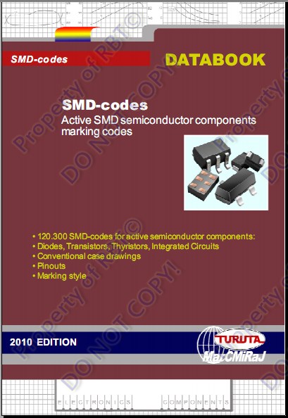
SMD-Codes Databook 2010 Edition

SMD-Codes Databook 2010 Edition


2010 edition SMD-code databook in PDF format from a known author Eugene Turuta presents the SMD-codes for active semiconductor components. This book includes now 120.300 SMD-codes for different semiconductors like diodes, thyristors, transistors and ICs.


Download Here:


RBT(c)2013
5000 Integrated Circuit Power Audio Amplifier
5000 integrated circuits - power audio amplifiers. A new data book in electronic format from a known author Eugene Turuta presents the integrated circuits - power audio amplifiers. This book includes about 5,000 integrated circuits - power (final) audio amplifiers.
 
Download Here: 
5000 Integrated Circuit Power Audio Amplifier
RBT(c)2013

Tuesday, April 16, 2013

5 Bands Graphic Equalizer


Based on the famous BA3822LS equalizer chip.


Introduction:

Many times when we hear a song we feel the need to change the parameters of the original EQ, adjusting this to our liking. While a song is recorded, mixed, equalized and mastered by experts, it is impossible to make a mix to suit the taste of each, which is different according to your personal settings and cultural environment that surrounds the listener. 
This is the moment we need an equalizer. Normally found three band EQ (Low, medium and high), but sometimes we fail to balance sound we want. 
To reduce this problem we have an equalizer that divide the audible aspect in more parts. In this paper we present a 5-band equalizer gives us the ability to "color" a little better our favorite songs.


What is an EQUALIZER?


The equalizer is a sound processor to split the original audio signal and modify the volume level independently. Each signal portion is called Band. Each band is responsible for increasing the volume of a certain frequency range. The human hearing range is from 20Hz , up to 20kHz . This EQ has 5 band-pass filters consist of capacitors and potentiometers that filter the desired frequency band. 
Band peaks are affected by this EQ: Bass ( 100Hz ), middle income ( 330Hz ), middle ( 1kHz ), upper middle ( 3.3kHz ) and high ( 10kHz ).

The materials of the 5-band stereo equalizer are very cheap and easily available. Check before starting the assembly of the circuit you have on hand all the necessary components for assembly. So the work is done faster and nicer, and there's nothing more boring than having to be traveling to get what you missed. For this we must carefully review the list of materials found in the PDF file and compare with the mask components, which we will use as a guide for the correct assembly of the circuit. It should be very careful when placing each component in place. Electrolytic capacitors, regulator and integrated circuits must respect the established polarity.


The integrated circuit BA3822LS stereo graphic equalizer is a five-point frequency control. BA3822LS has two channels within five center frequencies of each channel can be independently set using external capacitors. 
This IC has a wide feeding range, ranging from 3.5 volts to 14 volts DC. The integrated package is 24-pin SOIC or SZIP. This makes it an ideal choice for home stereo systems, for their videoke or for use as an equalizer in the car. 
Inside BA3822LS has 10 operational amplifiers. This facilitates the assembly of the circuit, reducing space and with a very affordable price.


Assembly:

We put all the resistors in place. The wrong placement of a part could cost us time and money. Then proceed to solder the resistors.


Next is to insert and solder all the capacitors, starting with ceramic type then Mylar. Since this capacitors doesn't have POLARITY, you can insert it in any direction..Just double check the value of the capacitors.
The 8 pins IC socket has a NOTCH on the other end to indicate the proper placement of the IC later..Follow the placement on the parts placement guide. 


Observed the placement of IC SOCKET!

Double check the VALUE of capacitors based on PARTS PLACEMENT GUIDE  printed on the PCB.

Electrolytic capacitors are POLARIZED devices . For this reason it is very important to check the PARTS PLACEMENT guide for the proper POLARITY before placement. 
To identify the polarity of a capacitor, note the white stripe with a minus sign, this is the negative lead of the capacitor. Also their polarity may be identified as its positive terminal is longer than the negative terminal. 
On the PARTS PLACEMENT GUIDE, a circle with a small DOT that indicates the negative lead of the Electrolytic capacitors.


Proper placement of Electrolytic capacitors.

 The circuit has a built-in rectifier diode, filter and regulator, so you can power it with AC or DC source..

Bridge rectified diode.

The regulator LM7809 delivers a voltage of 9 volts and a current of up to 1 amp. Our EQ regulator can be supplied with 12 - 24 VDC without any problems. Identifying a regulator should be noted that the letters LM corresponding to the mark of the component. In this case belongs to the American company National Semiconductor, which manufactures electronic components. The next two numbers ( 78 ) mean that the regulator is positive and the last two numbers ( 09 ), determine the output voltage of the regulator. In this case, 9V delivery. Remember that this controller can only be supplied with a voltage below 32 volts DC, if for some reason is supplied with a higher voltage, the regulator will burn. 
A regulator needs a DC voltage of at least 3 volts above the voltage delivery. For this reason we recommend feeding the circuit with at least 12 volts AC. If the transformer is too low, we will not get at least 3 volts above, necessary for the regulator to do its job and give us 9 volts.

LM7809, 9 volts regulator.

In the picture you can see the filter capacitor after bridge rectifier diode. This capacitor can be 1000 uF to 2200 uF at least 25VDC. Its function is to load and maintain voltage so that it does not fall at the end and beginning of each half cycle, thus converting alternating current (AC) into direct current (DC). can also observe three-pin connectors (GP). These connectors are very useful when removing the equalizer for maintenance or repair. The connector power input we have removed the center pin.
Power supply section.

The integrated circuit TL072 is a high performance dual op amp. 
As BA3822LS has no gain, ie outputs a signal of the same volume that you get, We make this operational to give a bit of gain to the signal. Resistors 2.2K going to the inverting inputs 2 and 6 respectively and 100K resistors ranging between inputs and outputs of the integrated, are responsible for the gain. 100K 2.2K Dividing, we get a gain of 45. 

If you need more gain, only 2.2K resistors change by about 1K. But if you just want to decrease the gain, can be altered 5.6k resistors, up to 10K. 
The TL072 can replace the JRC4558 , the TL082 or NE5532


Insert and solder the dual 50K potentiometers for the equalizer controls and the dual 20K potentiometer for the volume control. 

Before testing the circuit, inspect the PCB against the light, that has no short between tracks. Clean the PCB with a toothbrush and lacquer thinner, to remove grease and possible solder particles remain attached after soldering. 

Finished equalizer board.


 Download the schematic and PCB layout here: Schematic and PCB


 Original link HERE


Sunday, February 3, 2013

Working With USB SPI Programmer

Lots of people are asking for some pictorial guides on proper placement and mounting of SOIC/WSON8 chip on USB SPI. 

So here it is.just follow the guide closely..


Voltage selector and Pin numbering.


Be sure to properly insert the pins on ZIF socket.


24Cxx I2C EEPROM placement.

25/26 Series EEPROM Placement.

My preferred placement.

This is the MOST IMPORTANT and often IGNORED! Don't forget the INSULATOR!

SOIC8 to SOIC16 connection.


RBT(c)2012


Monday, January 9, 2012

TV/DVD I2C, SPI EEPROM Programmer Complete Tut!

Here is a video tutorials on how to install, register, activate and used TV/DVD I2C, SPI EEPROM Programmer.


 How to install and register:


Driver Installation:


How to work with the programmer:


Enjoy using your new programmer!


Download the latest installer HERE: 


RBT(c)2011


Wednesday, June 29, 2011

SunPlus DVD Mod

After some fiddling around, I found a way to mod my cheap China made DVD..


Here is a typical ACE DVD Player:


Inside of my ACE DVD Player.


This is how my DVD standby screen before the modification:


After the mods..


Saturday, June 4, 2011

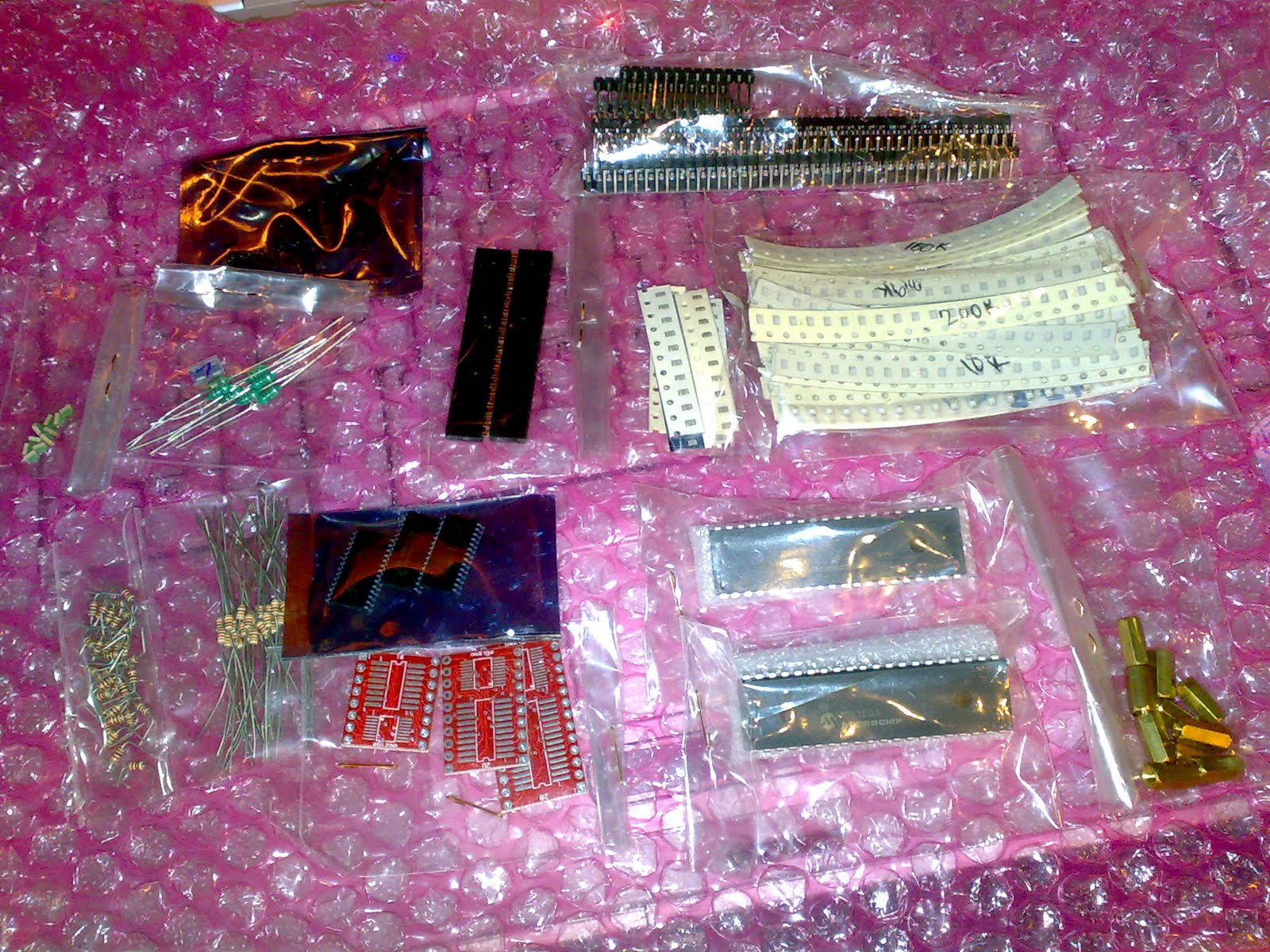
Some Parts To Play With

Just receive some hardware and electronic parts mostly SMD for me to play with...:D


PIC18F2550 SOIC, SMD resistors and caps..

PIC16F877, brass stand-off, coils, headers etc..

Tuesday, May 17, 2011

My First SMD, Double sided PCB

Here's is my first attempt of Double sided and SMD PCB using iron-on process..:D

Bottom Copper

Top Copper

 Using some SMD 0805, 1206, SMC_D, etc..

Wednesday, May 11, 2011

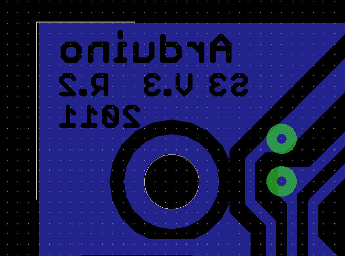
How to create TEXT outline in GROUNDPLANE?

Ever wonder how they create this beautiful TEXT outline on printed circuit board or PCB like this?
Text outline of PCB.

Here is my short video tutorial on how to create a TEXT OUTLINE on PCB using Cadsoft Eagle..

Watch this video.


Feel free to leave a comments if you need mode info's..:D


BR


Thursday, May 5, 2011

The New Facebook Scam, How to Get it Removed?

Scammers are making a lot many income from simple looking Facebook Applications. Now, Facebook is turning into Spambook rather than Facebook. One more spam has been added to this book. This new survey scam is a massive hit on Facebook and many people have been scammed.

This Scam claims to reveal your total Facebook Profile looks like the Orkut which displays recent users which saw your profile. The application will use your Facebook Wall to post spam messages onto user’s profile. This is totally SCAM. There is nothing like this which can actually tell how many times your profile has been viewed.

How this SPAM works:
You will see that your friend’s status update saying that he got to know how many people viewed his profile with the number. It will be like this:
_________________________________
My total facebook views are : 9632
Find out what your total profile views are: http:bit.ly/xxxx
________________________________
facebook virusIf you click on the link give, you will be directed to a Facebook Application where it will ask you to Allow the permissions to access your information. As soon as you click “Allow”, the application will automatically post these kinds of Status Updates on your wall which afterwards will infect your friends’ account. This way the SCAM spreads itself.
After the application post the Status Update, it will redirect you to a web page which claims that it can calculate the number of people who viewed your profile.

What you can do if you are victim of this Scam?

If you are infected with this Scam, firstly remove all the Status Updates which the application have automatically added. Then you have to remove the application to stop it accessing your Facebook profile. For this follow these steps:
  • Go to Account > Privacy Settings
  • You will see an option saying “Apps and Websites“. Below it there will be a link saying “Edit your settings” Click that link
  • New page will be opened, there you can see the Privacy options of Apps, Games and Websites which are connected with your Facebook Account.
  • The first option will be “Apps you use“. There will be a button saying “Edit Settings”. Click on it.
  • After you click it, you will see a list showing all the application to which your Facebook Account is connected.
  • Search the application saying “funnysweb“. Remove it from your Facebook Account.
Now you have successfully removed the spamming application. We hope that this post helped you, do consider sharing this with others to spread the awareness and help infected peoples. ;)

Introduction to AT Commands

AT commands are instructions used to control a modem. AT is the abbreviation of ATtention. Every command line starts with "AT" or "at". That's why modem commands are called AT commands. Many of the commands that are used to control wired dial-up modems, such as ATD (Dial), ATA (Answer), ATH (Hook control) and ATO (Return to online data state), are also supported by GSM/GPRS modems and mobile phones. Besides this common AT command set, GSM/GPRS modems and mobile phones support an AT command set that is specific to the GSM technology, which includes SMS-related commands like AT+CMGS (Send SMS message), AT+CMSS (Send SMS message from storage), AT+CMGL (List SMS messages) and AT+CMGR (Read SMS messages).

Note that the starting "AT" is the prefix that informs the modem about the start of a command line. It is not part of the AT command name. For example, D is the actual AT command name in ATD and +CMGS is the actual AT command name in AT+CMGS. However, some books and web sites use them interchangeably as the name of an AT command.
Here are some of the tasks that can be done using AT commands with a GSM/GPRS modem or mobile phone:
  • Get basic information about the mobile phone or GSM/GPRS modem. For example, name of manufacturer (AT+CGMI), model number (AT+CGMM), IMEI number (International Mobile Equipment Identity) (AT+CGSN) and software version (AT+CGMR).
  • Get basic information about the subscriber. For example, MSISDN (AT+CNUM) and IMSI number (International Mobile Subscriber Identity) (AT+CIMI).
  • Get the current status of the mobile phone or GSM/GPRS modem. For example, mobile phone activity status (AT+CPAS), mobile network registration status (AT+CREG), radio signal strength (AT+CSQ), battery charge level and battery charging status (AT+CBC).
  • Establish a data connection or voice connection to a remote modem (ATD, ATA, etc).
  • Send and receive fax (ATD, ATA, AT+F*).
  • Send (AT+CMGS, AT+CMSS), read (AT+CMGR, AT+CMGL), write (AT+CMGW) or delete (AT+CMGD) SMS messages and obtain notifications of newly received SMS messages (AT+CNMI).
  • Read (AT+CPBR), write (AT+CPBW) or search (AT+CPBF) phonebook entries.
  • Perform security-related tasks, such as opening or closing facility locks (AT+CLCK), checking whether a facility is locked (AT+CLCK) and changing passwords (AT+CPWD).
    (Facility lock examples: SIM lock [a password must be given to the SIM card every time the mobile phone is switched on] and PH-SIM lock [a certain SIM card is associated with the mobile phone. To use other SIM cards with the mobile phone, a password must be entered.])

  • Control the presentation of result codes / error messages of AT commands. For example, you can control whether to enable certain error messages (AT+CMEE) and whether error messages should be displayed in numeric format or verbose format (AT+CMEE=1 or AT+CMEE=2).
  • Get or change the configurations of the mobile phone or GSM/GPRS modem. For example, change the GSM network (AT+COPS), bearer service type (AT+CBST), radio link protocol parameters (AT+CRLP), SMS center address (AT+CSCA) and storage of SMS messages (AT+CPMS).
  • Save and restore configurations of the mobile phone or GSM/GPRS modem. For example, save (AT+CSAS) and restore (AT+CRES) settings related to SMS messaging such as the SMS center address.
Note that mobile phone manufacturers usually do not implement all AT commands, command parameters and parameter values in their mobile phones. Also, the behavior of the implemented AT commands may be different from that defined in the standard. In general, GSM/GPRS modems designed for wireless applications have better support of AT commands than ordinary mobile phones.

In addition, some AT commands require the support of mobile network operators. For example, SMS over GPRS can be enabled on some GPRS mobile phones and GPRS modems with the +CGSMS command (command name in text: Select Service for MO SMS Messages). But if the mobile network operator does not support the transmission of SMS over GPRS, you cannot use this feature.

Basic Commands and Extended Commands

There are two types of AT commands: basic commands and extended commands.

Basic commands are AT commands that do not start with "+". For example, D (Dial), A (Answer), H (Hook control) and O (Return to online data state) are basic commands.

Extended commands are AT commands that start with "+". All GSM AT commands are extended commands. For example, +CMGS (Send SMS message), +CMSS (Send SMS message from storage), +CMGL (List SMS messages) and +CMGR (Read SMS messages) are extended commands.

Wednesday, May 4, 2011

How to Use Microsoft HyperTerminal to Send AT Commands to a Mobile Phone or GSM/GPRS Modem?

What is Microsoft HyperTerminal?

Microsoft HyperTerminal is a small program that comes with Microsoft Windows. You can use it to send AT commands to your mobile phone or GSM/GPRS modem. It can be found at Start -> Programs -> Accessories -> Communications -> HyperTerminal. If you cannot find it and you are using Windows 98, then probably you have not installed it. You can go to Control Panel -> Add/Remove Programs -> Windows Setup tab -> Communications list box item -> Details button to install MS HyperTerminal.

Before you start programming your SMS application, you may want to check if your mobile phone, GSM/GPRS modem and SIM card are working properly first. The MS HyperTerminal is a handy tool when it comes to testing your GSM devices. It is a good idea to test your GSM devices beforehand. When a problem occurs, sometimes it is difficult to tell what causes the problem. The cause can be your program, the GSM device or the SIM card. If you test your GSM device and SIM card with MS HyperTerminal and they operate properly, then it is very likely that the problem is caused by your program.

For Linux users, minicom can be used instead of HyperTerminal.


The Procedure for Sending AT Commands to a Mobile Phone or GSM/GPRS Modem Using MS HyperTerminal

To use MS HyperTerminal to send AT commands to your mobile phone or GSM/GPRS modem, you can follow the procedure below:

  1. Put a valid SIM card into the mobile phone or GSM/GPRS modem. You can obtain a SIM card by subscribing to the GSM service of a wireless network operator.
  2. Connect your mobile phone or GSM/GPRS modem to a computer and set up the corresponding wireless modem driver. You should find the wireless modem driver in the CD or disk that was provided by the manufacturer. If the manufacturer does not provide such CD or disk with your mobile phone or GSM/GPRS modem, you can go to the manufacturer's web site and see whether the wireless modem driver can be downloaded there. If the wireless modem driver cannot be found on the web site, you can still use Windows' standard modem driver.
  3. Run MS HyperTerminal by selecting Start -> Programs -> Accessories -> Communications -> HyperTerminal.
  4. In the Connection Description dialog box, enter a name and choose an icon you like for the connection. Then click the OK button.

Figure 5. The screenshot of MS HyperTerminal's Connection Description dialog box in Windows 98.


  1. In the Connect To dialog box, choose the COM port that your mobile phone or GSM/GPRS modem is connecting to in the Connect using combo box. For example, choose COM1 if your mobile phone or GSM/GPRS modem is connecting to the COM1 port. Then click the OK button.

    (Sometimes there will have more than one COM port in the Connect using combo box. To know which COM port is used by your mobile phone or GSM/GPRS modem, follow the procedure below:

    In Windows 98:
    Go to Control Panel -> Modem. Then click the Diagnostics tab. In the list box, you can see which COM port the mobile phone or GSM/GPRS modem is connected to.

    In Windows 2000 and Windows XP:
    Go to Control Panel -> Phone and Modem Options. Then click the Modems tab. In the list box, you can see which COM port the mobile phone or GSM/GPRS modem is connected to.)


Figure 6. The screenshot of MS HyperTerminal's Connect To dialog box in Windows 98.


  1. The Properties dialog box comes out. Enter the correct port settings for your mobile phone or GSM/GPRS modem. Then click the OK button.

    (To find the correct port settings that should be used with your mobile phone or GSM/GPRS modem, one way is to consult the manual of your mobile phone or GSM/GPRS modem. Another way is to check the port settings used by the wireless modem driver that you installed earlier.

    To check the port settings used by the wireless modem driver on Windows 98, follow these steps:
    a. Go to Control Panel -> Modem.
    b. Select your mobile phone or GSM/GPRS modem in the list box.
    c. Click the Properties button.
    d. The Properties dialog box appears. The Maximum speeds field on the General tab corresponds to HyperTerminal's Bits per second field. Click the Connection tab and you can find the settings for data bits, parity and stop bits. Click the Advanced button and you can find the setting for flow control.

    To check the port settings used by the wireless modem driver on Windows 2000 and Windows XP, follow these steps:
    a. Go to Control Panel -> Phone and Modem Options -> Modems tab.
    b. Select your mobile phone or GSM/GPRS modem in the list box.
    c. Click the Properties button.
    d. The Properties dialog box appears. Click the Advanced tab and then click the Change Default Preferences button.
    e. The Change Default Preferences dialog box appears. The Port speed field on the General tab corresponds to HyperTerminal's Bits per second field. You can also find the setting for flow control on the General tab. On the Advanced tab, you can find the settings for data bits, parity and stop bits.)


Figure 7. The screenshot of MS HyperTerminal's Properties dialog box in Windows 98.


  1. Type "AT" in the main window. A response "OK" should be returned from the mobile phone or GSM/GPRS modem.
    Type "AT+CPIN?" in the main window. The AT command "AT+CPIN?" is used to query whether the mobile phone or GSM/GPRS modem is waiting for a PIN (personal identification number, i.e. password). If the response is "+CPIN: READY", it means the SIM card does not require a PIN and it is ready for use. If your SIM card requires a PIN, you need to set the PIN with the AT command "AT+CPIN=".


Figure 8. The screenshot of MS HyperTerminal's main window in Windows 98.


If you get the responses above, your mobile phone or GSM/GPRS modem is working properly. You can start typing your own AT commands to control the mobile phone or GSM/GPRS modem.

Further details about how to use AT commands to send and receive SMS messages will be provided in the following sections.

Introduction to GSM / GPRS Wireless Modems

A GSM modem is a wireless modem that works with a GSM wireless network. A wireless modem behaves like a dial-up modem. The main difference between them is that a dial-up modem sends and receives data through a fixed telephone line while a wireless modem sends and receives data through radio waves.

A GSM modem can be an external device or a PC Card / PCMCIA Card. Typically, an external GSM modem is connected to a computer through a serial cable or a USB cable. A GSM modem in the form of a PC Card / PCMCIA Card is designed for use with a laptop computer. It should be inserted into one of the PC Card / PCMCIA Card slots of a laptop computer.

Like a GSM mobile phone, a GSM modem requires a SIM card from a wireless carrier in order to operate.

Computers use AT commands to control modems. Both GSM modems and dial-up modems support a common set of standard AT commands. You can use a GSM modem just like a dial-up modem.

In addition to the standard AT commands, GSM modems support an extended set of AT commands. These extended AT commands are defined in the GSM standards. With the extended AT commands, you can do things like:
  • Reading, writing and deleting SMS messages.
  • Sending SMS messages.
  • Monitoring the signal strength.
  • Monitoring the charging status and charge level of the battery.
  • Reading, writing and searching phone book entries.
The number of SMS messages that can be processed by a GSM modem per minute is very low -- only about six to ten SMS messages per minute.

What is a GPRS Modem?

A GPRS modem is a GSM modem that additionally supports the GPRS technology for data transmission. GPRS stands for General Packet Radio Service. It is a packet-switched technology that is an extension of GSM. (GSM is a circuit-switched technology.) A key advantage of GPRS over GSM is that GPRS has a higher data transmission speed.

GPRS can be used as the bearer of SMS. If SMS over GPRS is used, an SMS transmission speed of about 30 SMS messages per minute may be achieved. 

This is much faster than using the ordinary SMS over GSM, whose SMS transmission speed is about 6 to 10 SMS messages per minute. A GPRS modem is needed to send and receive SMS over GPRS. Note that some wireless carriers do not support the sending and receiving of SMS over GPRS.

If you need to send or receive MMS messages, a GPRS modem is typically needed.

Which is Better: Mobile Phone or GSM / GPRS Modem?

In general, a GSM/GPRS modem is recommended for use with a computer to send and receive messages. This is because some mobile phones have certain limitations comparing to GSM/GPRS modems. Some of the limitations are described below:
  • Some mobile phone models (example: Ericsson R380) cannot be used with a computer to receive concatenated SMS messages.

    What is a concatenated SMS message?
    A concatenated SMS message is a message that contains more than 140 bytes. (A normal SMS message can only contain at most 140 bytes.) Concatenated SMS works like this: the sender's mobile device breaks a message longer than 140 bytes into smaller parts. Each of these parts are then fitted in a single SMS message and sent to the recipient. When these SMS messages reach the destination, the recipient's mobile device will combine them back to one message.

    What is the cause of the problem?
    When the mobile phone receives the SMS messages that are parts of a concatenated SMS message, it combines them to one message automatically. The correct behavior should be: when the mobile phone receives the SMS messages that are parts of a concatenated SMS message, it forwards them to the computer without combining them.

  • Many mobile phone models cannot be used with a computer to receive MMS messages. Because when they receive a MMS notification, they handle it automatically instead of forwarding it to the computer.
  • A mobile phone may not support some AT commands, command parameters and parameter values. For example, some mobile phones do not support the sending and receiving of SMS messages in text mode. So, the AT command "AT+CMGF=1" (it instructs the mobile phone to use text mode) will cause an error message to be returned. Usually GSM/GPRS modems support a more complete set of AT commands than mobile phones.
  • Most SMS messaging applications have to be available 24 hours a day. (For example, an SMS messaging application that provides ringtone downloading service should be running all the time so that a user can download ringtones any time he/she wants.) If such SMS messaging applications use mobile phones to send and receive SMS messages, the mobile phones have to be switched on all the time. However, some mobile phone models cannot operate with the battery removed even when an AC adaptor is connected, which means the battery will be charged 24 hours a day.
Besides the above issues, mobile phones and GSM/GPRS modems are more or less the same for sending and receiving SMS messages from a computer. Actually, you can consider an AT-command-enabled mobile phone as "GSM/GPRS modem + keypad + display + ...".
There is not much difference between mobile phones and GSM/GPRS modems in terms of SMS transmission rate, since the determining factor for the SMS transmission rate is the wireless network.

Thursday, April 28, 2011

Gadget Wish List

I'm dying to have this baby....:D


Rotacraft Mini Drill


Rotacraft Mini Drill with Variable Transformer and 60 Accessories


A comprehensive and versatile Mini drill set that is ideal for model making, electronics, engraving and small DIY jobs. 


It comprises:  
 
RC18 Pen-like 12v Mini Drill with variable speed - 8000 - 18000rpm with 4 collet chucks (1.00, 2.35, 3.00 & 3.10mm) 220/240v Mains to 12v transformer with 3 pin plug.

Accessories including drill bits, polishing wheel shank,  2 x Big Fleece polishing wheels, 2 x Small Fleece Polishing Wheels, 20 x diamond points, 10 x grinding stones, 1 x mandrel with screw top, 5 x carborundum cutting discs, 2 x sanding drum mandrels, 3 x sanding drums, 2 x wire wheel brushes and 1 x nylon pencil brush.

All contained in a smart metal case with clear lid.

Do Energy Savers Really Work?


One example of the so called "Power Saver."

So what's inside of this high-tech device?

A fancy LED's with big AC capacitor...:D

Add don't be surprised if only ONE wire is connected...
that's what we call "BLACK MATTER"


Soaring electric bills may entice your interest toward plug-in energy saver devices. But be aware that you may spend a lot of money for nothing because these energy savers cannot change your appliance’s power consumption- or lower your electric bill.   

Reducing Current Consumption Does Not Reduce Power Bills

Electric power savers for the home have in the recent past become quite popular (through some brute advertising). The companies who are busy promoting them claim that by just plugging one in to any mains socket or near your energy meter, you can reduce your home electric bill by as much as 40 to 50%.

That seems too good to be true, doesn't it? Let’s analyze their claims through a step-wise discussion.

Companies promoting and boasting their power saving equipment claim that their products are able to save domestic residential power consumption by employing an "active power factor correction" method on the supply line. The concept seems pretty impressive as the concept is true and legally accepted. But practically, you will find that it’s not feasible. A thorough technical discussion perhaps won’t be required as it can be proved through the following simple verifications:

There are basically two kinds of load that exists in every house: one that’s resistive like incandescent lamps, heaters etc.; and the other that’s capacitive or inductive like ACs, refrigerators, computers, etc. PF, or power factor, may be defined as the ratio of the real power that’s being consumed by the load to the apparent power that’s being actually used by the load.

It’s given by the formula:

PF = Real Power (Watts) /Apparent Power (VA),

Therefore, Real Power (Watts) = Apparent Power × PF = Voltage × Ampere × PF

Ideally a PF = 1, or unity, for an appliance defines a clean and a desired power consumption, because then the dissipated output power becomes equal to the applied input power.

In the above formula you can find that if PF is less than 1, the amperes (current consumption) of the appliances increases, and vice versa.

With AC resistive loads, the voltage is always in phase with the current and constitutes an ideal power factor equal to 1. However, with inductive or capacitive loads, the current waveform lags behind the voltage waveform and is not in tandem. This happens due to the inherent properties of these devices to store and release energy with the changing AC waveform, and this causes an overall distorted wave form, lowering the net PF of the appliance.

The above problem may be solved by installing a well-calculated inductor/capacitor network and switching it automatically and appropriately to correct these fluctuations. A power saver unit is designed exactly for this purpose, and to an extent may successfully do so. This correction is able to bring the level of PF very close to unity, thus improving the apparent power to a great extent. An improved apparent power would mean less CURRENT consumption by all the domestic appliances.

So far everything looks fine, but what’s the use of the above correction? The utility bill that we pay is never for the Apparent Power- it’s for the Real Power. The below given example will prove this statement:

Consider a refrigerator having a rated Real Power of 100 watts at 220 V AC has a PF = 0.6. The expression explained above becomes:

100 = 220 × A × 0.6

Therefore, A = 0.75 Ampere

Now suppose after appropriate power corrections, if the PF is brought to about 0.9, the above result will now show as:

100 = 220 × A × 0.9

And A = 0.5 Ampere

In the second expression we clearly witness a reduced current consumption by the refrigerator, but interestingly in both the above cases, the Real Power remains the same, i.e. the refrigerator continues to consume 100 watts, and therefore the utility bill remains the same. This simply proves that although the PF correction done by an energy saver unit may decrease the Amperage of the appliances, it can never bring down their power consumption and the electric bill amount.

Power Saving with Resistive Loads

Since a resistive load does not carry a PF issue, we can formulate and express their power as:

P = UI, where P is the power, U is the applied input mains voltage, and I is the resultant consumed current.

The above expression simply proves that as long as the voltage and the current are constant, the consumed power will also be constant. However, if there’s any rise in the input voltage because of a fluctuation, then as explained above your appliances will be forced to consume a proportionate amount of power. This becomes more apparent because current, being a function of voltage, also rises proportionately. However, this rise in the power consumption will be negligibly small; the following simple math will prove this.
Consider a bulb consuming 100 watts of power at 220 volts. This simply means at 240 volts it will use up about 109 watts of power. The rise is just of around 9% and since such fluctuations are pretty seldom, this value may be furthermore reduced to less than 1%, and that is negligible.

Thus the above discussions convincingly prove that energy savers can never work and the concept is not practically feasible. Energy savers are a scam.